Via Aspromonte, 4 Busto Arsizio (VA)
 Fiber Optic Sensors
In this section you can find some technical notes about fiber optics and their applications in the sensors filed.
Fiber Optics: an introduction | ||
What is a fiber optic | ||
|
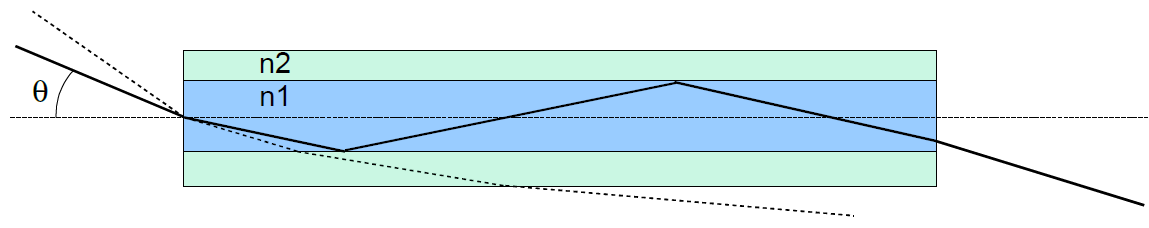
A typical optical fiber is shown in Figure A: the fiber is constituted by an inner part (core) with a refractive index n1 and an outer part (called cladding) with refractive index n2. The optical fibers are made of glass or polymers and are usually coated with a protective sheath (coating). | ||
| The typical diameter of a single mode optical fiber for telecommunications with acrylate coating is 125 μm, that become 250 μm considering also the protective sheath. However, there are optical fibers specially designed for sensors, with the smaller diameter (80 μm o 60 μm) to be less invasive in case for example of medical applications or embedding into composite materials, and with special coating with particular characteristics of mechanical strength and temperature resistance. Exploiting the characteristics of the guided light it is possible to realize a multiplicity of fiber optic sensors that operate according to different principles. The particularity of these devices lies in the fact that the optical fiber is not used as a simple connecting cable but is itself the "sensitive" element, that does not require the use of any electric power in the measurement zone. The optical fibers for applications in the field of telecommunications and sensors are usually made of glass, single-mode type, used in the infrared optical band (wavelengths comprised between 1300 and 1600 nm). | ||
Fiber optic sensors | ||
| There are different types of fiber optic sensors, which adapt to different measurement environments and requirements.Some examples:
| ||
Main benefits in the sensors field | ||
| ||
Fiber optic sensors: what they can detect | ||
| Fiber optic sensors are suitable for a wide variety of measures, depending on their type, the optical parameter that is used and the adopted initerrogation technique.
The Fiber Bragg Grating (FBG) is a device that uses the wavelength of light. It essentially acts as a strain gauge. Suitably coupled to a structure, embedded into a composite material, in a polymer or in an elastomer, it allows to create sensors for localized deformation (flexion, traction, compression, torsion) and vibration measurements. Exploiting the characteristics of the host material, in particular of the elastomers, you can measure weight, pressure and acceleration. Its features also allow temperature measurements. With interferometric sensors that exploit the properties of coherence, phase and polarization of light, in addition to the measurable parameters with the FBG sensors, you can also measure displacement and distance. The measurement with interferometric sensors takes place in an integral manner along the optical path of the measuring beam. Sensors based on scattering phenomena allow to measure with continuity along a certain section of optical fiber both temperature and deformation. Depending on the measurement technique you can get very different performance in terms of spatial resolution, acquisition speed, measurement distance. | ||
The Fiber Bragg Grating (FBG): principle of operation | ||
|
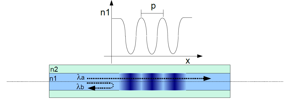
A Fiber Bragg Grating (Figure B) is a periodic modulation of pitch (p) of the refractive index (n1) of the fiber: it acts as a mirror that reflects the light of a specific wavelength (λb): the wavelengths different from λb, indicated with λa, are not reflected. A variation of the pitch (p) of the refractive index modulation (n1) changes the wavelength of the reflected light: the Bragg grating acts as a sensor when it is fixed to a structure that transmits its deformation to the optical fiber, by changing the pitch (p) of the grating. Analyzing the wavelength of the reflected light is then possible to determine the deformation applied to the grating. The reflected wavelength also varies depending on the temperature of the Bragg grating, due to both the expansion of the glass of which the optical fiber is made, and the variation of refraction of the glass as a function of temperature. Therefore, the Bragg grating can also be used as a temperature sensor. In all those cases where the temperature variations can disturb the strain measurement it is necessary to compensate the temperature effect by means of another sensor. | ||
To know more | ||
The FBG sensor formula
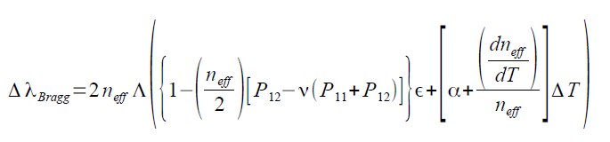
The periodic variations of the refraction index in the fiber optic core, that can be obtained in photosensitive fibers designed for sensing applications, determine the reflection of the guided light at a specific wavelength λBragg said the Bragg wavelength. Every variation of the refraction index along the optical path of the light produces infact the reflection of a small part of the incident light. This happens at every "line" of the peridic structure impressed into the core (the FBG). All the reflected components whose wavelength satisfies the relationship: λBragg = 2 neff Λ (where Λ is the grating period and neff is the refraction index of the fiber optic core for the specific guided mode) sum up in phase, therefore the light reflected by the FBG sensor is characterized by a well defined wavelength which is a function of the grating period Λ. In a smplified form, the FBG sensor formula reduces to λBragg = kε ε + kT ΔT | ||
| Any phisical parameter acting on the fiber so to modify the grating period is then detectable as a reflected wavelength variation. By replacing the typical values of the coefficients in the FBG formula, the vavelength shift due to strain and temperature can be calculated. They are of the oreder of: 1 pm/μe 10 pm/°C From the formula it is also evident that it's impossible to separate the two effects, mechanical and thermal, form one another.
| ||
| Download the pdf: FBG sensors [EN] AN01_fbgsens_[EN] AN02_shapesensing_[EN] Sensori in fibra ottica [IT] | ||